
Investment Casting Tolerances: Specify by Feature, Not by Slogan
Turn assembly requirements into a clear drawing that separates as-cast geometry, machined interfaces and final inspection.
Guidance for project discussions. Exact requirements and manufacturing feasibility are reviewed against your drawing.
What to take away
- Start with assembly function and identify the features that control it.
- Distinguish casting-stage geometry from final machined requirements.
- Agree measurement references, delivery condition and acceptance before tooling.
Why one tolerance number is not enough
A capability statement cannot replace a drawing review. The Investment Casting Institute design guide notes that achievable casting tolerances vary with factors including material, size and configuration. Its published examples are guidance, not a promise for another foundry or your component.
Begin by deciding what the part must do in its assembly. Then identify the dimensions and geometric relationships that control that function. Ask the supplier to review those requirements feature by feature, with exceptions and machining proposals stated explicitly.
Separate functional interfaces from general shape
Mark the drawing in three groups: features that control assembly, geometry intended to remain as cast and surfaces with appearance or texture requirements. Some features may belong to more than one group; identify that overlap instead of leaving it implicit.
- Assembly interfaces: mating faces, bores, threads and mounting locations.
- General geometry: envelopes, nonmating contours and clearance areas.
- Surface requirements: visible faces, specified texture and protected areas.
Assign requirements according to function. Do not apply the tightest interface tolerance to the entire part without an engineering reason.
Make the inspection references unambiguous
Define the datums and relationships that represent how the part locates in the assembly. Check that the drawing and model use consistent units, feature definitions and revisions. Ask how the supplier proposes to locate the casting for machining and for final inspection.
If the reference surface changes during manufacture, distinguish the temporary manufacturing reference from the final drawing datum. Review any proposed datum change with the responsible designer. A convenient shop reference should not silently replace the functional reference used to accept the finished component.
Separate casting-stage and finished dimensions
Clearly mark which features require machining. Provide the final requirements and ask the casting and machining teams to agree the stock allowance and locating strategy. Avoid adding one universal allowance to every surface without that review.
If separate casting and finished-part drawings are used, connect their identifiers and revisions. Make clear which drawing governs each delivery stage. If one drawing covers both stages, use unambiguous notes and feature callouts so a casting-stage measurement cannot be mistaken for the final acceptance result.
Agree the condition in which parts are measured
State the required delivery condition, including specified machining, treatment and surface processing. Decide which measurements belong in the sample report and which checks will apply to recurring production.
- What drawing revision controls the report?
- How will the part be located during measurement?
- Which features need individual results?
- How are appearance and texture assessed separately?
- Who reviews a result outside the agreed requirement?
Resolve unclear methods before a dispute occurs. A measured value is most useful when its feature, reference and acceptance limit are identifiable.
Turn the review into an approved specification
Ask the supplier to return a requirement matrix listing accepted callouts, proposed machining, requested drawing changes and open questions. Review the exceptions with engineering before approving tooling or production.
Use samples to verify the agreed plan rather than to discover what the drawing meant. Preserve the approved drawing, inspection approach and any accepted deviations as controlled records. When a functional requirement changes, review its effect on casting, machining and inspection together instead of updating only the nominal dimension.
Apply this to your component.
Share the drawing, material and finished-part requirements so the manufacturing route can be reviewed together.
Further reading
Make the next connection.
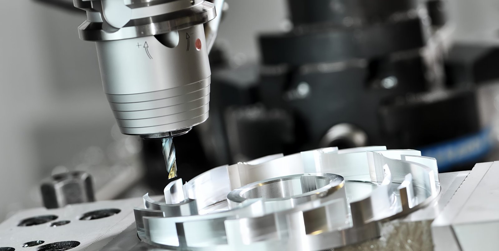 CASTING + CNC
CNC Machining Investment Castings: Plan the Critical Interfaces
A drawing-review guide to machining scope, locating surfaces, stock allowance and the handoff from casting to finished part.
Read the guide
Investment Casting RFQ Checklist: What to Send for a Useful Quote
Build an enquiry package that gives engineering and purchasing the same starting point, with unknowns clearly identified.
Read the guide