01 / The process explained
What is silica sol investment casting?
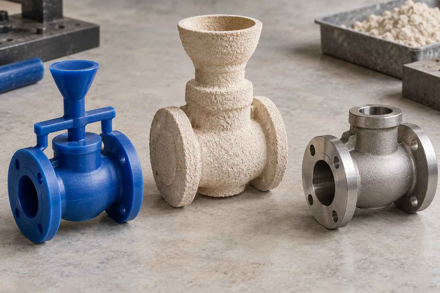
Silica sol investment casting is a lost-wax process that uses colloidal silica as a binder in a refractory ceramic shell. A wax pattern defines the geometry, successive ceramic coats create the mold, and the wax is removed before molten alloy enters the cavity. The shell is broken away after solidification.
Silica sol is an aqueous dispersion of very small silica particles. It binds the refractory material; it is not the metal being cast. The refractory flour, stucco and binder together form the shell system. Ransom & Randolph describes its Levasil binder as an approximately 30% solids aqueous dispersion, but that product value is not a universal slurry recipe. [1]
For a buyer, the useful outcome is a near-net-shape starting point. The final drawing still determines whether bores, threads, locating faces or sealing surfaces need machining. Discuss these interfaces when selecting the casting route, rather than after tooling has been approved.
02 / Eight process stages
From wax pattern to finished component
The sequence below is a manufacturing overview. Shell materials, coat count and thermal cycles are selected for the actual alloy and part. The Investment Casting Institute describes shell building as repeated slurry dipping, stucco application and drying to form a layered mold. [2]
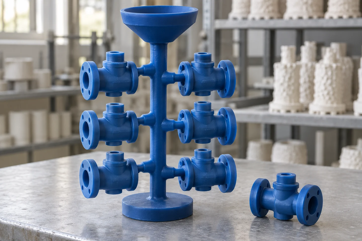
The wax assembly establishes geometry and connects each pattern to its runner system.
01—04
Build the mold
Pattern geometry · primary coating · controlled drying
05—08
Deliver the component
Shell preparation · metal processing · final verification
01
Tooling & wax
Prepare the tool, make the wax pattern and check dimensions, surfaces and pattern condition.
02
Tree assembly
Attach patterns to a runner system. Plan gates for filling, feeding and subsequent removal.
03
Primary coating
Wet the pattern with the primary slurry and apply fine refractory stucco to establish the mold face.
04
Shell build & drying
Add backup coats with drying between applications. Check recessed areas as well as exposed surfaces.
05
Dewax & shell preparation
Remove the wax, then fire and prepare the shell using the qualified process for the mold and alloy.
06
Melting & pouring
Verify alloy composition and control the melt, shell preparation and filling conditions.
07
Knockout & finishing
Remove the shell and runners, clean the casting and complete the specified heat treatment.
08
Machining & inspection
Finish critical interfaces and verify the agreed dimensional, material and surface requirements.
NovaCast’s process description connects wax production, shell building, shell preparation and pouring. Its published temperatures describe its route; they should not be copied into another foundry’s work instruction without qualification. [3]
03 / Slurry & shell control
Why shell quality starts with slurry control
The primary coat reproduces the wax surface. Backup coats build the shell needed to survive handling, dewaxing and pouring. A useful control plan therefore covers both surface reproduction and shell performance. Selecting a silica-sol binder alone does not establish that the process is in control.
Ransom & Randolph’s slurry-control guidance lists viscosity, density, slurry and binder solids, binder pH, gelation and antifoam checks. [4] Interpret those measurements against the supplier’s formulation and the foundry’s validated operating limits; a flow-cup time has little meaning without the cup, temperature and measurement method.
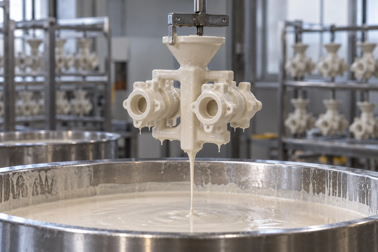
Consistent wetting and drainage help form a continuous primary coat.
01
Slurry consistency
Record the measurement method and operating range. Track additions and trends, not only a pass/fail reading.
02
Coverage & drainage
Check wetting, drainage and coating continuity at pockets, slots and transitions.
03
Layer integrity
Confirm intercoat condition before redipping and look for loose refractory or damaged mold faces.
A separate R&R process study examines slurry viscosity, immersion dwell time and drainage technique. [5] The practical implication is to control how the shell is made as well as what it is made from.
04 / Drying & lead time
Drying is a process variable, not just waiting time
During drying, water must leave the coating while the binder develops the bonds needed for shell strength. Recesses, closely spaced patterns and thicker sections may dry differently from exposed areas. A surface that looks dry does not prove that the whole assembly is ready for its next coat.
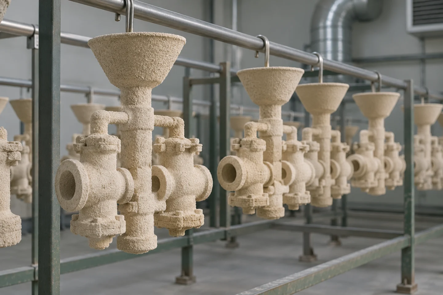
Space between assemblies supports airflow; readiness between coats depends on the whole shell system.
The 2024 Investment Casting Institute conference paper on slurry formulation identifies temperature, humidity, airflow, part geometry and shell-system composition as interacting influences on coat drying. [6] This explains why a fixed number of hours is a weak specification without the assembly and process conditions.
Enhanced binder systems may permit different drying conditions: R&R describes Primcote as allowing faster primary-coat drying with lower humidity and/or more air circulation. [7] That product-specific benefit is not permission to use the same settings for every binder.
Ask for a process-based lead time
Separate tooling, sample production, shell building, treatment, machining and approval. Ask which stage controls the schedule and how the supplier confirms readiness between coats.
05 / Material & precision
Materials, tolerances and surface finish
Silica-sol casting is used for stainless steel and other cast alloys; suitability also depends on the foundry’s melting and treatment capability. ELCEE lists stainless and duplex grades alongside several steel and non-ferrous families. [8] Specify the cast grade, governing material requirements and delivery condition instead of ordering only a generic label such as stainless steel.
Supplier data show why capability should be reviewed rather than assumed. ELCEE lists CT6 linear dimensions and CT7 wall thicknesses for its route, while KeLin publishes DCTG 5–6 and Ra 3.2–6.3 µm as its own technical capability. [8][9] These are separate supplier statements, not a universal guarantee or an automatic equivalence between tolerance systems.
For an RFQ, mark the features that must function as cast and those that require machining. Define the datum system, surface-finish measurement locations and acceptance criteria. Review our casting-tolerance and CNC-interface guides when preparing the drawing.
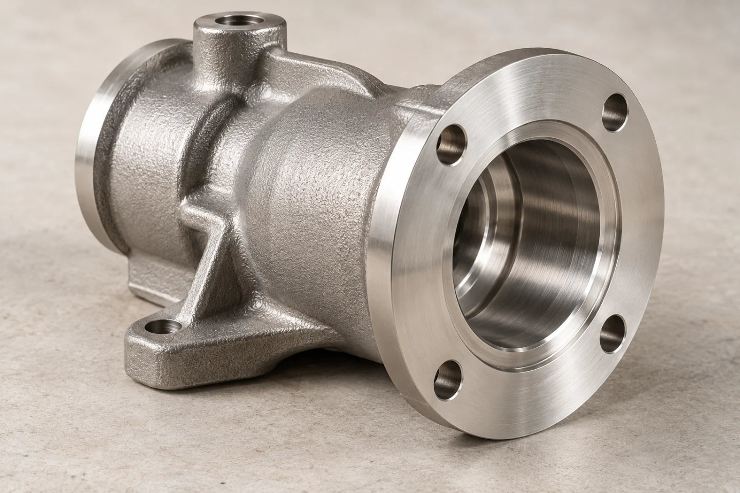
A cast shape and its machined interfaces perform different jobs. Define both on the finished-part drawing.
01
Cast geometry
Discuss feature size, wall transitions, cores, distortion and gate-removal locations.
02
Machined interfaces
Identify sealing faces, fits, threads, bores and the stock needed for finishing.
03
Acceptance evidence
Agree sample reports, material records and any application-specific tests before production.
06 / Route & cost comparison
When to choose silica sol—and what to compare
Use silica sol as a candidate when a complex cast shape and controlled surface reproduction can simplify the finished component. The economic question is the total delivered part: tooling, casting, treatment, machining, yield, inspection and repeat quantity all matter. This comparison framework is our engineering purchasing synthesis, not a price promise.
RMC describes the binder choice as relevant to surface roughness and dimensional accuracy, and notes the shell-making cycle as a limitation. [10] Discuss those trade-offs against the actual drawing rather than assuming that one binder name determines cost or quality.
| Route | What to check | When to compare |
|---|---|---|
| Silica-sol shell | Review primary-coat reproduction, drying control and dimensional capability. | Complex cast geometry with defined surfaces and interfaces. |
| Water-glass or hybrid shell | Confirm the exact shell system, sample finish and machining requirement. | An alternative quotation when the drawing permits its demonstrated capability. |
| Machining from stock | Compare material removal, setup count and access to internal features. | Simple geometry, early prototypes or quantities that do not justify casting tooling. |
Compare these routes using the same finished-part specification and order quantity. A hybrid shell should be identified explicitly; it is not the same specification as an all-silica-sol shell.
07 / Quality & defect review
Turn quality requirements into an acceptance plan
The following is a suggested review checklist. It distinguishes a visible issue from a confirmed root cause: a supplier should investigate the wax, shell and metal process before choosing a corrective action.
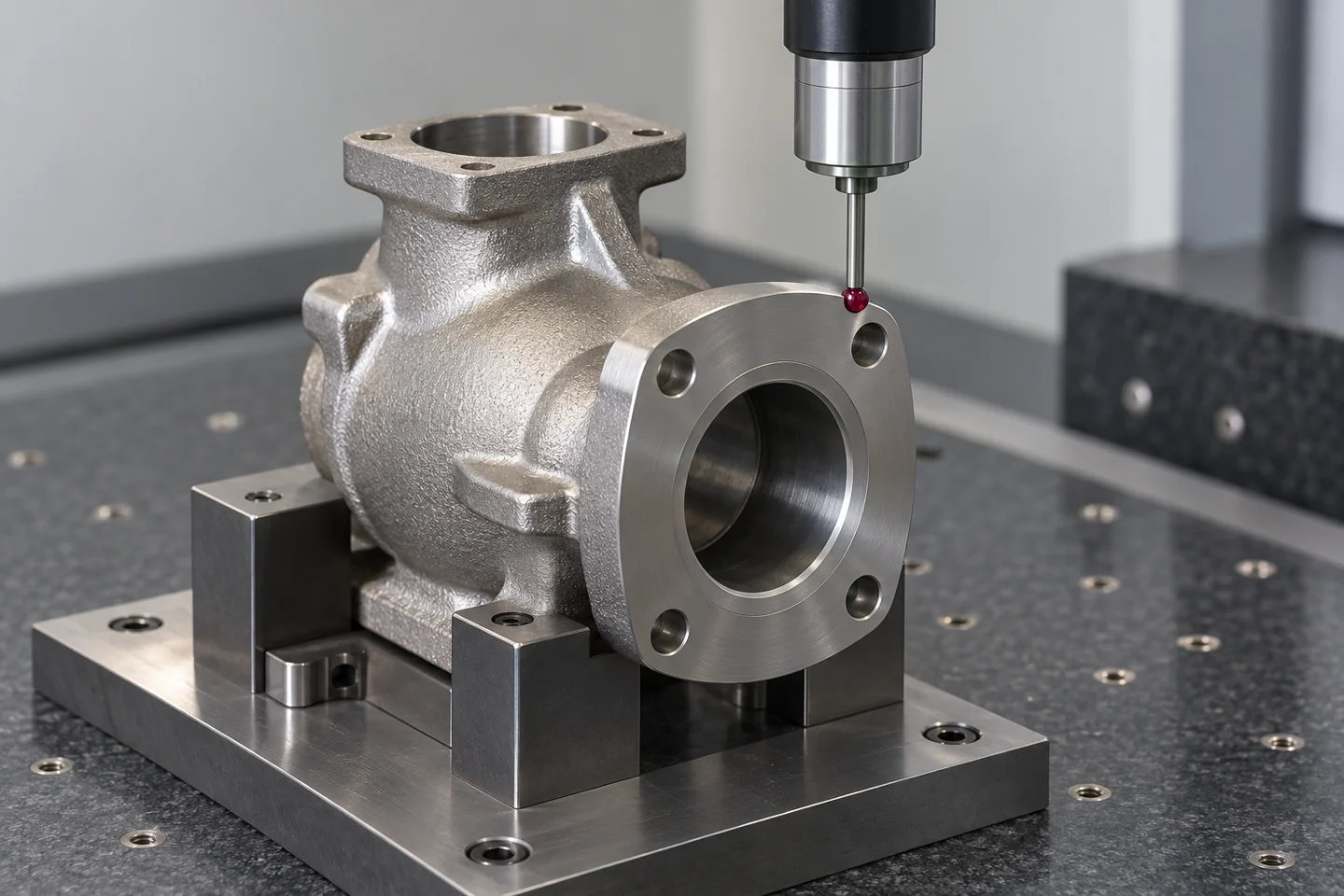
Inspection starts with named features, a datum system and agreed acceptance evidence.
01
Surface pits or raised features
Review wax condition, coating coverage, drainage and the location of the defect.
02
Ceramic inclusions
Review shell integrity, loose refractory, cleanliness and handling before pouring.
03
Short fill or internal shrinkage
Review filling and feeding design, section transitions and the qualified thermal conditions.
04
Distortion or dimensional drift
Compare pattern measurements, assembly support, casting condition and finishing operations.
A purchasing acceptance matrix should name the drawing revision, features to measure, required material records and responsible approver. If pressure testing or nondestructive examination is required, specify method, coverage and acceptance criteria. Sampling and testing scope must match the application.
08 / RFQ checklist
A better RFQ for silica-sol precision castings
A complete enquiry helps a foundry distinguish confirmed requirements from assumptions. Our suggested starting package is:
01
A dimensioned drawing and 3D model with the same revision.
02
Cast alloy, material specification and required delivery condition.
03
Sample, first-order and expected repeat quantities.
04
Critical dimensions, datums, machined surfaces and finish requirements.
05
Inspection, testing, traceability and sample-approval scope.
06
Target milestones, destination and packing requirements.
Ask the quotation to separate tooling and one-time charges from recurring part cost, identify the proposed shell system and list open technical questions. Send the drawing to toway casting for a manufacturing review, or use the detailed RFQ checklist to organize the enquiry.
ANSWERS FOR ENGINEERS & BUYERS
Frequently asked questions
Is silica sol casting the same as lost-wax casting?
Silica-sol casting is one version of lost-wax investment casting. It describes the binder used in the ceramic shell; lost wax describes how the expendable pattern is removed.
How many shell coats are needed?
There is no single coat count for every part. The foundry selects and validates the shell build for the pattern geometry, refractory and binder system, alloy and casting conditions.
Does silica-sol casting eliminate machining?
Some surfaces can remain as cast. Functional fits, sealing faces, threads or tight dimensional requirements may still need secondary operations defined on the drawing.
How long does the process take?
The schedule includes tooling, wax production, shell building and drying, casting, treatment, machining and sample approval. Request a staged schedule for the actual part and shell system.
What tolerance or roughness can I specify?
State the functional requirements and measurement locations on the drawing, then obtain feature-specific capability confirmation. A supplier’s general range is not acceptance evidence for a different component.
THE RESEARCH BEHIND THIS GUIDE
Sources & further reading
Technical and foundry sources reviewed on 4 October 2026. Process parameters belong to the stated supplier or study; the purchasing checklists are our synthesis.
- Ransom & Randolph — Levasil colloidal silica
Binder identity and one commercial solids-content example. - Investment Casting Institute — Shell Building
Repeated dipping, stucco application and drying. - NovaCast — Silica Sol Casting
Wax-to-shell process sequence; published parameters remain supplier-specific. - Ransom & Randolph — Casting Connection, Jan–Feb 2019
Page 2: slurry-control measurements. - Ransom & Randolph — How Process Variables Impact Ceramic Shell Properties
Viscosity, dwell time and drainage variables. - ICI 2024 Technical Conference — Slurry Formulation and Drying Times/Cost
Temperature, humidity, airflow, geometry and shell formulation. - Ransom & Randolph — Primcote binder
Product-specific drying flexibility. - ELCEE — Investment castings, silica sol process
Material families and supplier-specific tolerance data. - KeLin — Silica Sol Investment Casting
Supplier-specific DCTG and surface-roughness ranges. - RMC — Silica Sol Binder in Investment Casting
Binder influence and shell-cycle trade-offs.
START WITH THE FINISHED PART
Bring the drawing. Define the route.
Share the alloy, quantity and critical interfaces. Start with a manufacturing review that connects casting, machining and inspection.